Arduino Screen Controller for Raspberry Pi Part 3 Hardware Final
A few months ago I setup a web browser based dashboard running on a Raspberry Pi, displaying weather, time and transit information. It worked out well, but it’s success revealed another problem. Turning the screen on and off multiple times a day was getting old.
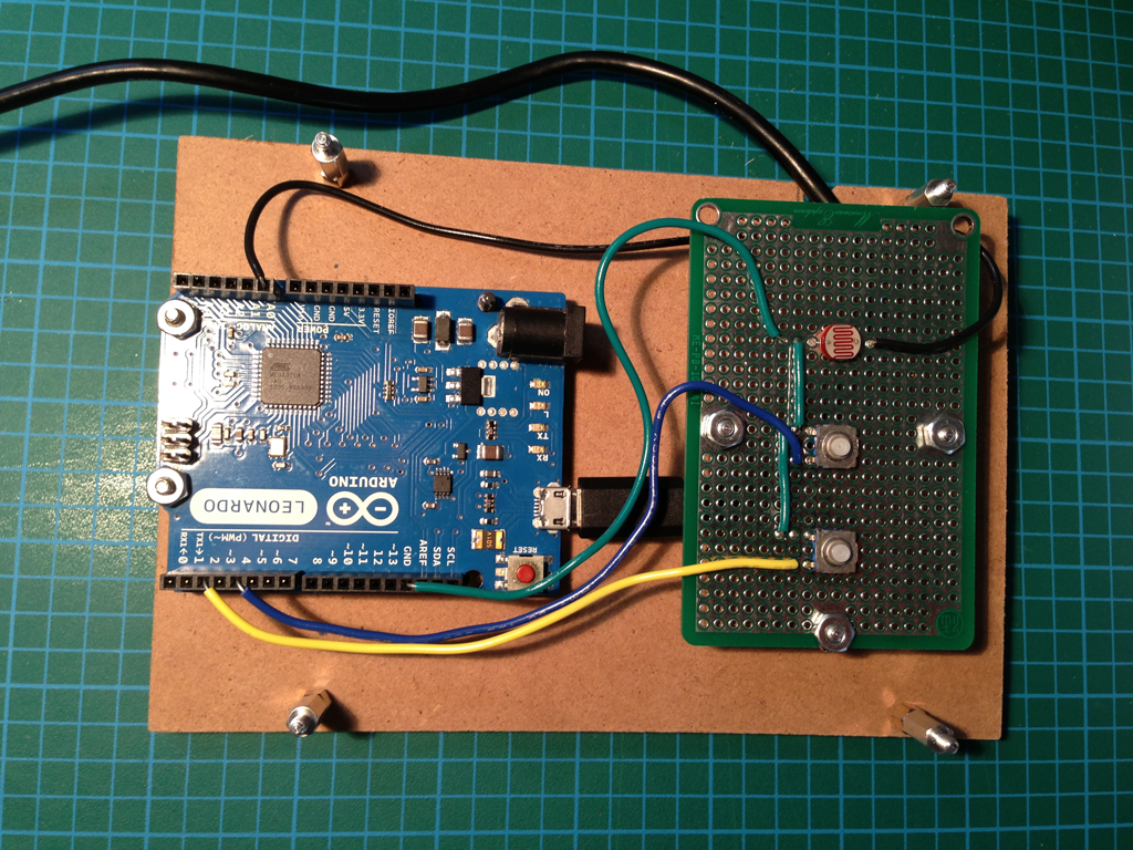
So I did what any technically inclined person would do. I decided to create a device to turn the screen on and off by responding to dramatic changes in ambient light. The device would also provide a manual power toggle and button to refresh the browser.
This is part 3 of 3 describing the final hardware that was built from the prototype.
- Arduino Screen Controller for Raspberry Pi Part 1 Hot Keys
- Arduino Screen Controller for Raspberry Pi Part 2 Hardware Prototype
- Arduino Screen Controller for Raspberry Pi Part 3 Hardware Final
Although intended to be used with a Raspberry Pi, the screen controller can be used to emulate a USB keyboard and send any desired keystrokes.
Hardware
- Arduino Leonardo
- Micro to Standard A USB cable, to connect Ardunino
- Breadboard, for prototyping
- 2 switches
- 1 light sensor
- Wire to connect components
- Shadow box picture frame, 4in x 6in approx 1.5in deep
- Micro to Standard A USB cable, to connect Ardunino
- Rubber feet
- Perf board
- Assorted stand offs, bolts and nuts
Tools
- Soldering iron
- Solder
- Wire snips
- Tools for wire stripping
- Hobby knife
- Printer
Links
- Github Arduino Screen Controller
Description
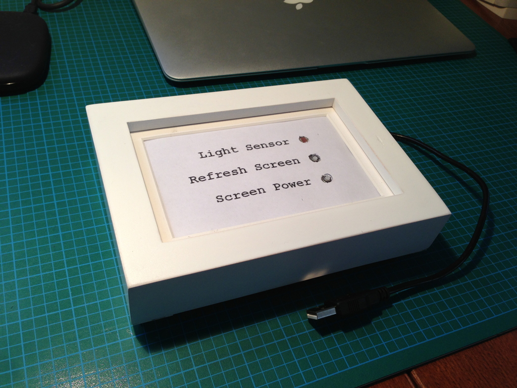
A ‘shadow box’ style picture frame was used as a case. It provided an attractive container and allowed a ‘picture’ with instructions to appear next to the buttons.
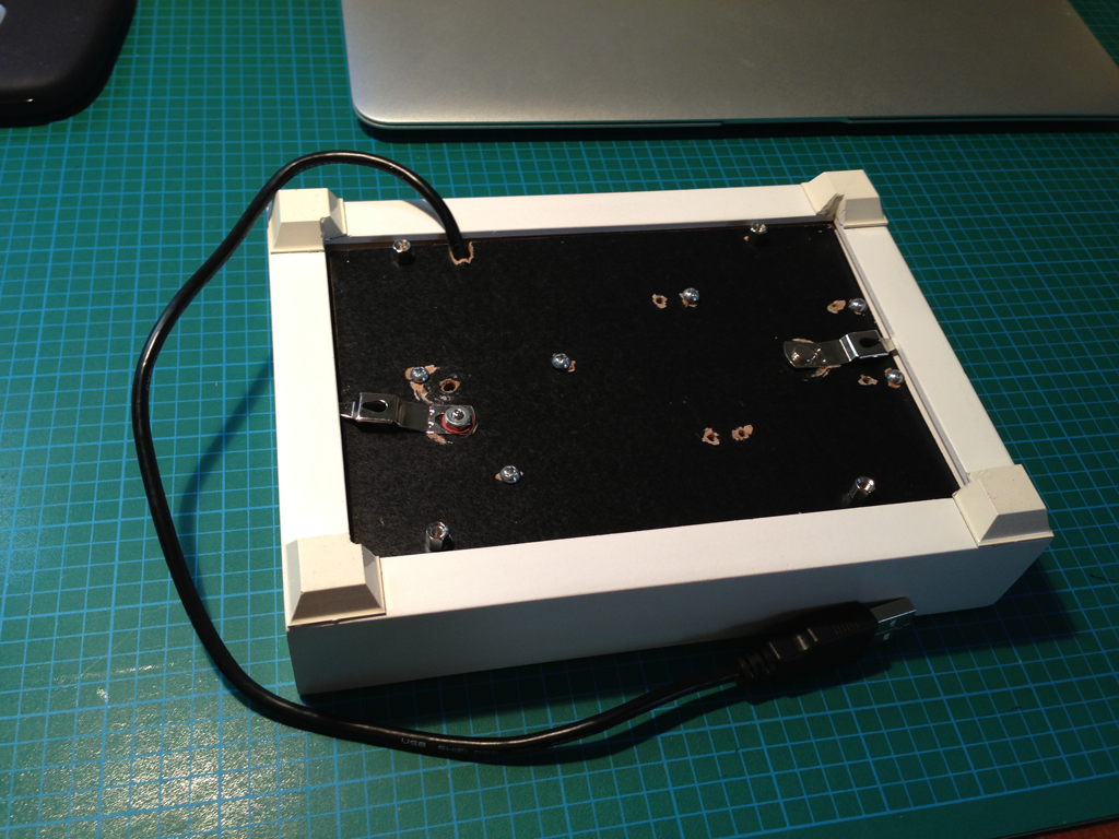
The rubber feet lifted the box up to provide a gap for the USB cable to exit the frame. They were a little large and had to be trimmed with the hobby knife to allow the frame to be reassembled.
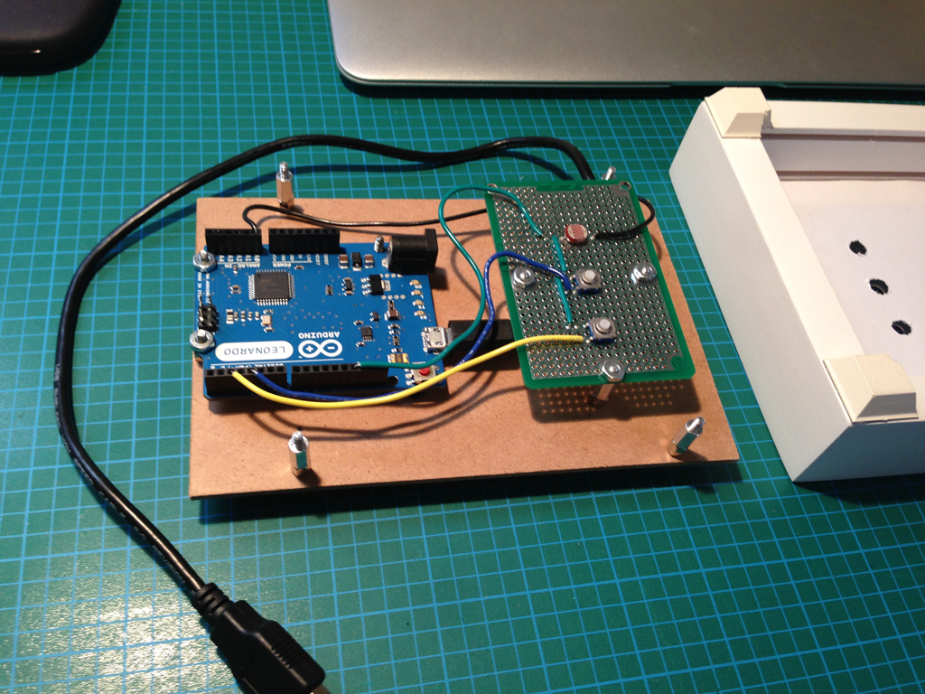
The prototype was disassembled and components, buttons and sensor, placed to match the ‘picture’ print out. At this point some experimentation is required to properly place everything in the picture frame.
Using a larger picture frame is an option, but with proper placement it is possible to arrange and fit all the components in a 4in x 6in frame.
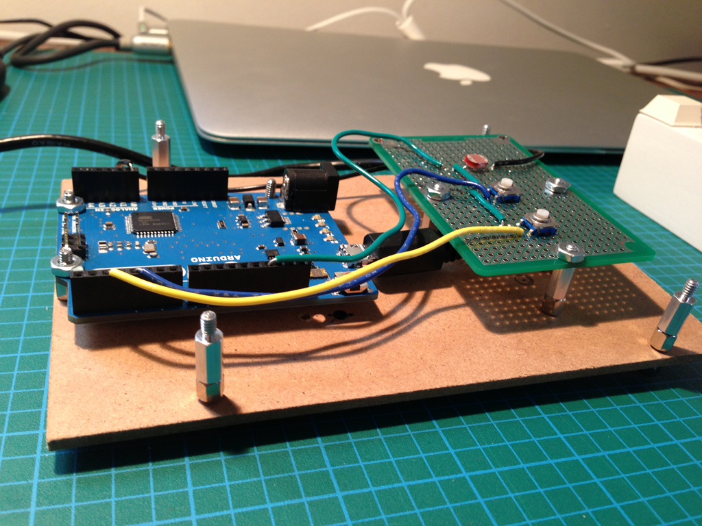
The biggest challenge was to acquire and arrange the proper stand offs and bolts. Stand offs were used around the perimeter of the picture frame backing to provide contact with the mat and hold it in place. The perf board was placed higher then the Arduino so that it was in contact with the front, the buttons and sensor were in the proper position and the USB cable was unobstructed.
Another thing to consider is the placement of the picture frame backing retainer clips. One of the two clips had to be moved to allow the standoffs to be positioned correctly.
Here is the final product: